
It's very important for those of us who create our own symbols.

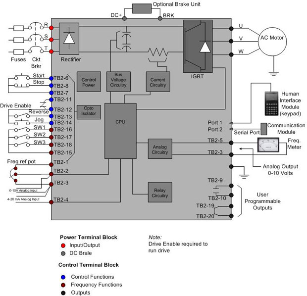
You should look it up in HELP and get familiar with it. HDR1 means 'horizontal drive parent' and HDR2 means 'horizontal drive child'.)ĪCADE has a specific naming convention for symbols. (In your case, HDR literally means 'horizontal drive'. Also, it has to go in the fourth character position the first character is reserved for the symbol's ladder orientation while the second and third character positions denote the symbol's component type. Using a 3 or 4 or any other digit could affect ACADE's behavior with that symbol. In ACADE, 1=parent and 2=child, for all parent-child symbols. Also every time I chose Horizontal child as the type but next time I open the symbol builder window it is written Horizontal parent so it does not save my modifications. At this point the application keeps showing a tag duplicate message and do not recognize those elements as one single device. The blocks work perfectly when alone until I put the second one with the same tag. I tried to use a couple parent/parent and a parent/child one, tag1 and tag 1, tag1 and tag2 subsequently. I looked some video tutorials and also checked how a default relay/contact couple is done. So I need the Autocad Electrical to recognize those two symbols as a parent(power) and a child (control) elements and to create a cross-reference between and to write only one single component in the bill of materials as well. A completed drive is now in your schematic page and you could create a macro for that drive for the next time.I'm trying to create a VFD Altivar two custom symbols: one for power schematic (parent) sheet and the other one for the control schematic. These circuits are typically different for everybody, but generically this will convey the idea. Once I have those, I will go and modify the circuits for my control to what I need for the drive. For this next step I will go in then and modify my power terminals and circuits. Then go in and select the Mfg Part tab to view the circuits. I named mine VFD1 or whatever you would like to name your drive. Once you have done that, the symbol has several terminals and circuits created for you. With the branch and control drawn, you can insert your black box symbol as shown. You can do these in separate objects or as shown here, one black box symbol. Along with that, have control circuits that you want to use drawn in as well. Start by having your motor branch drawn out. I am going to show you how to create a VFD for your schematic page with just that symbol. One of the lesser known or used symbols in SOLIDWORKS Electrical is the black box.


 0 kommentar(er)
